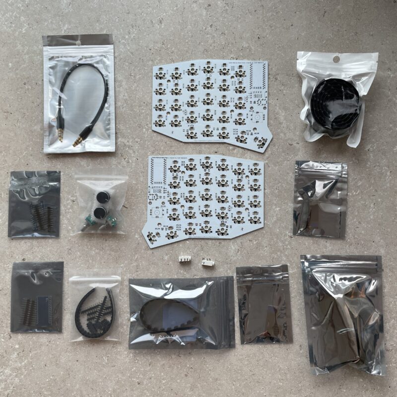
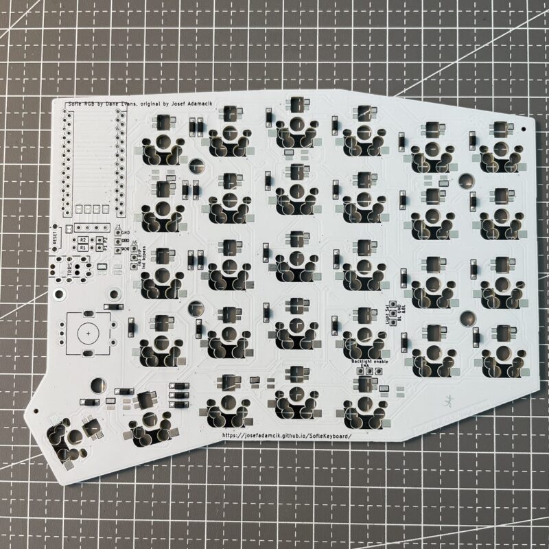
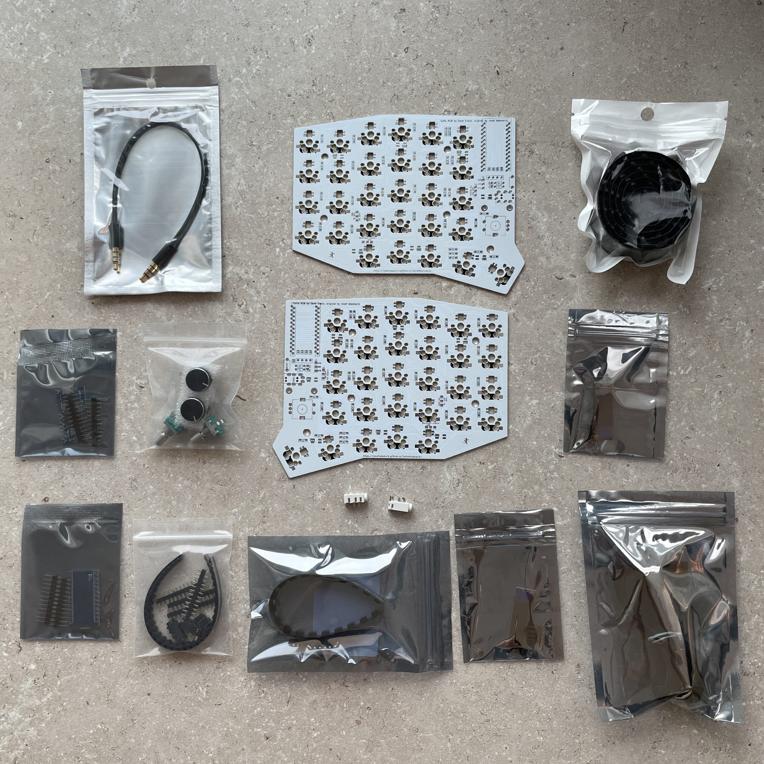
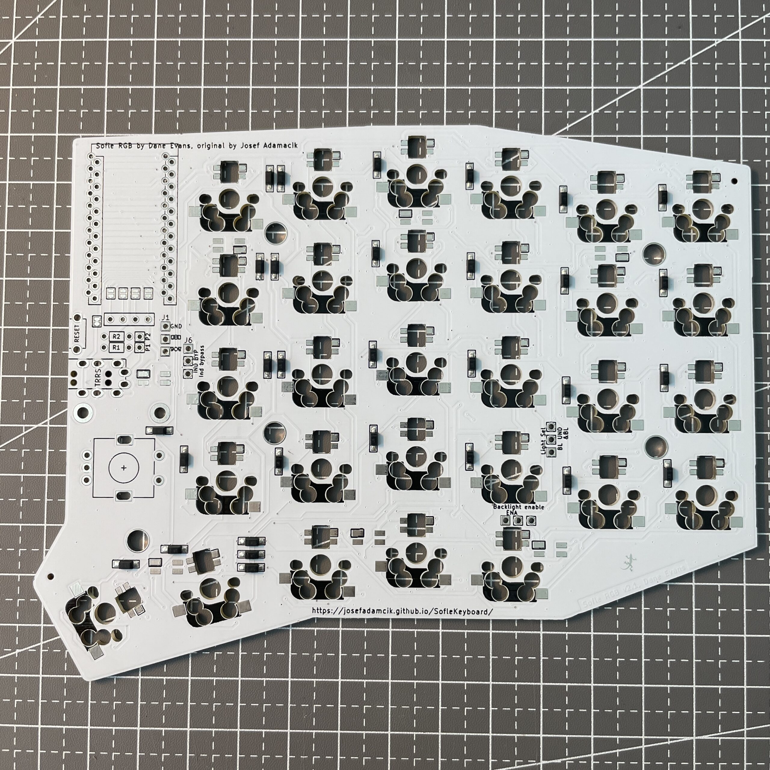
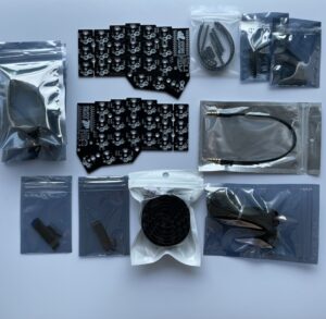
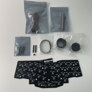
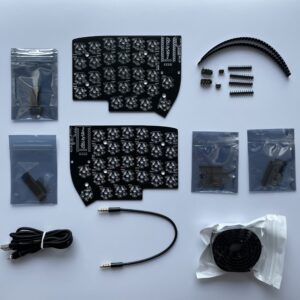
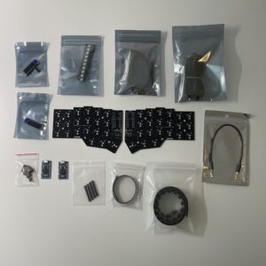
Sofle RGB v2.1 PCB + Parts Kit includes:
- White PCBs for left hand and right hand
- SMD diodes
- 58x Gateron or Kailh hotswap socket for MX switches
- 2x OLED display modules
- 2x TRRS jacks
- 1x TRRS cable
- 2x Reset tactile switches
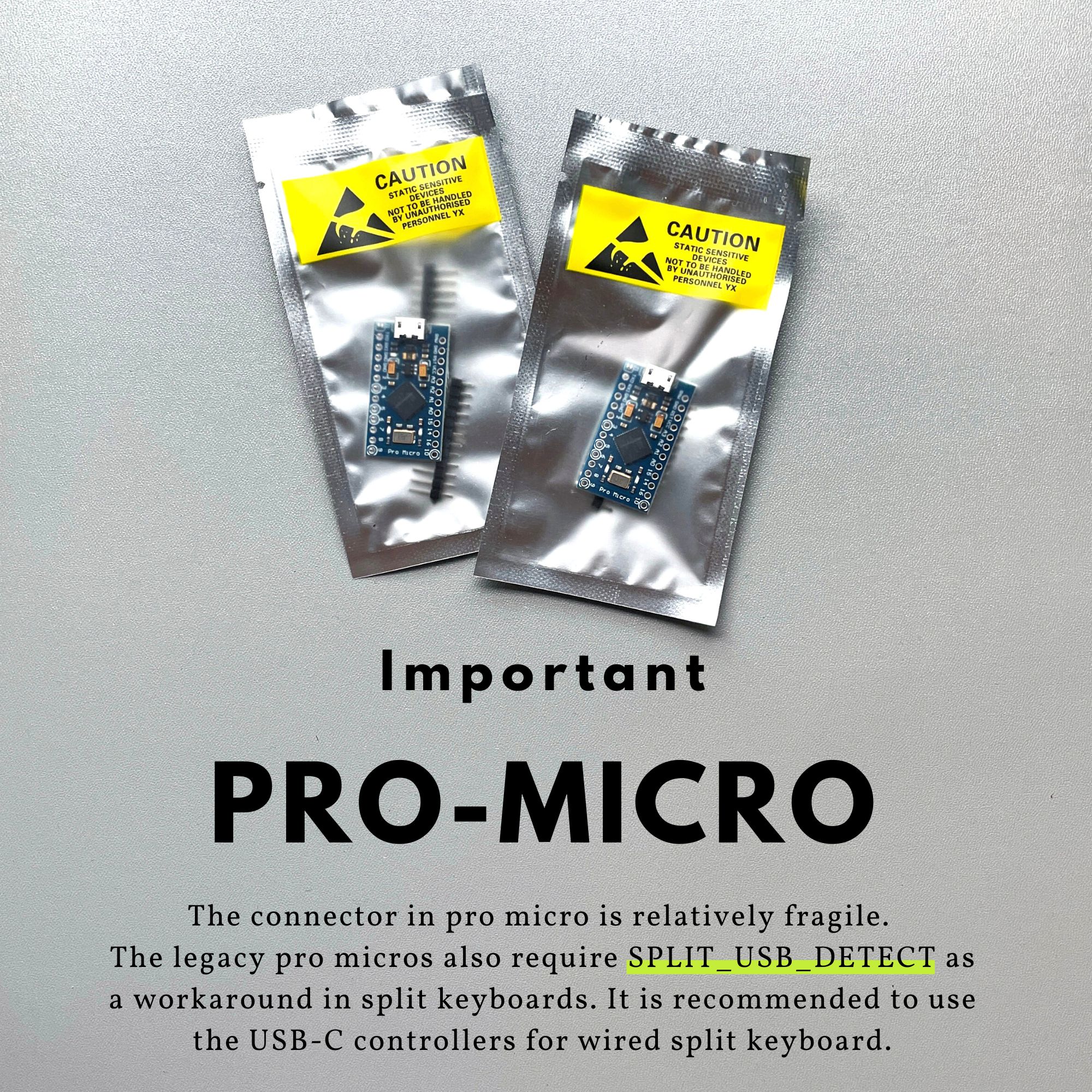
- 2x Pro micro controller boards (optionally upgrade to USB Type-C)
- 2x rotary encoder
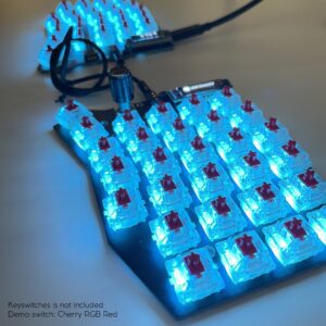
- 72x RGB LED SK6812mini-3535
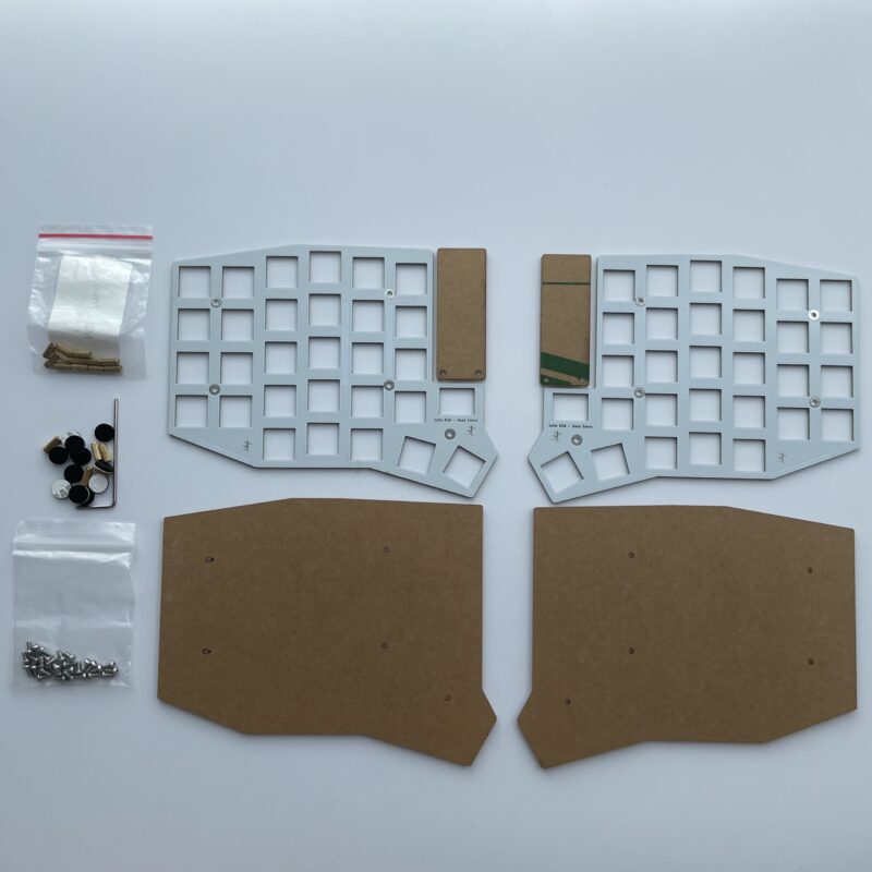
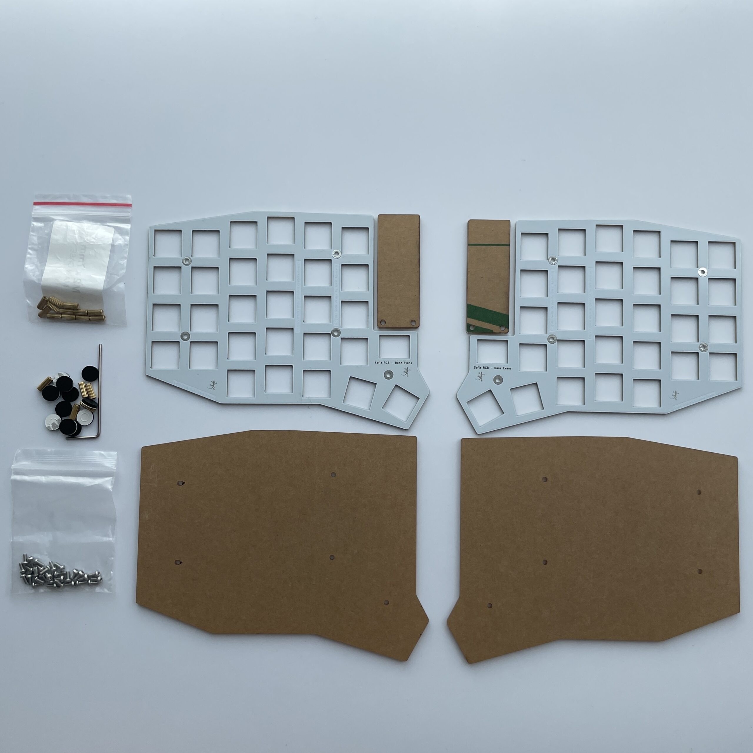
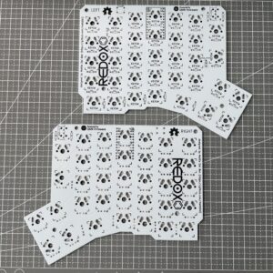
Plate / Case includes:
- FR4 white top plate
- Clear (transparent) acrylic bottom plate
- Clear (transparent) OLED acrylic cover
- M2 spacers
- M2 screws
- Silicone rubber feet
Custom order
- If you have a special request, please message me for a custom order
Important notes
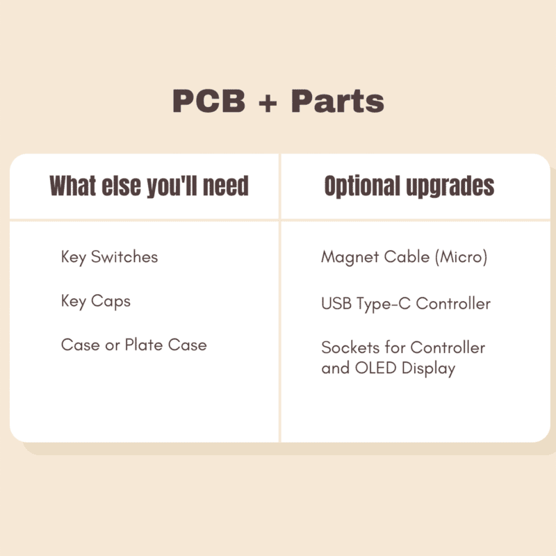
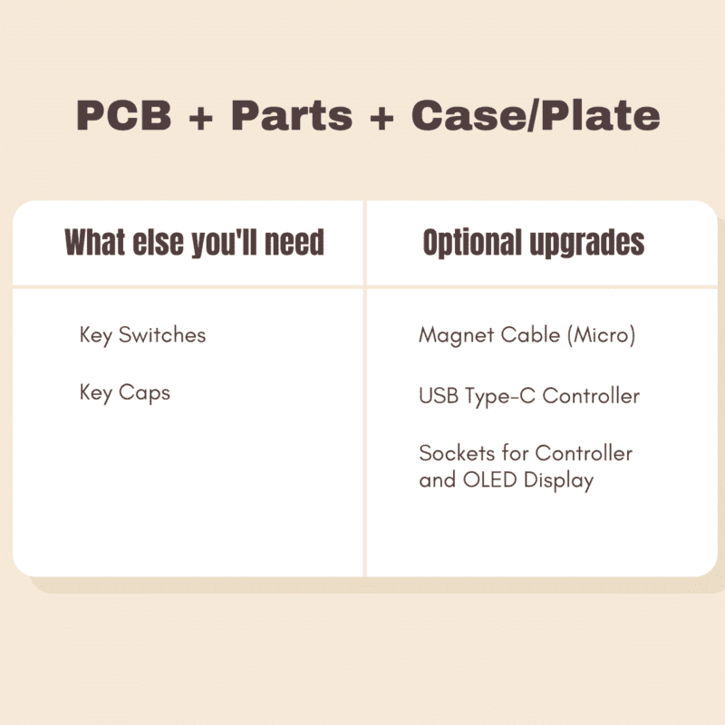
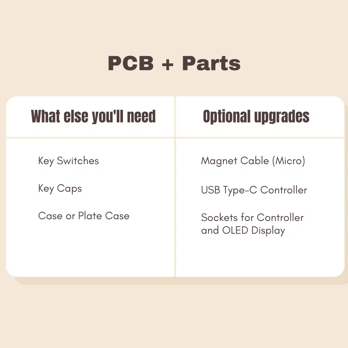
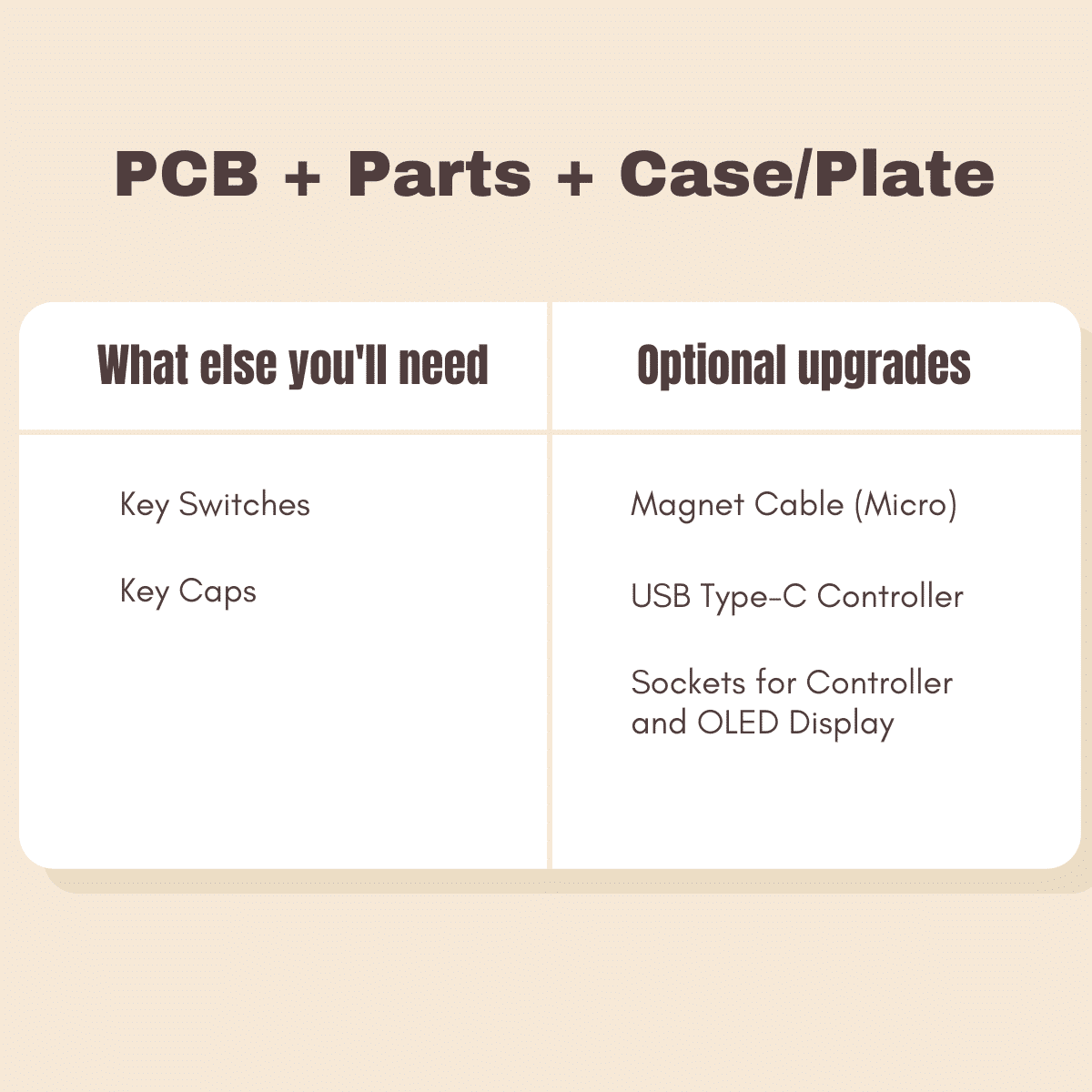
- You will need to buy a case, keycaps, and key switches separately.
- You will need to solder this by yourself if you do not add the soldering service.
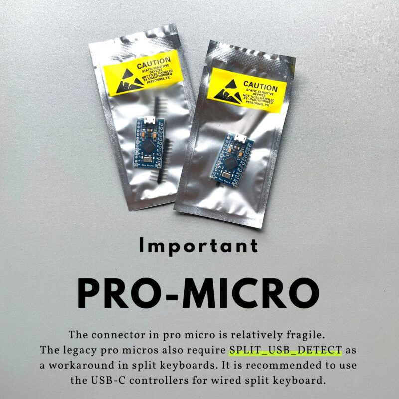
- The micro USB micro-B connector in pro micro is relatively fragile. The legacy pro micros also require SPLIT_USB_DETECT as a workaround in split keyboards. It is recommended to use the USB-C controllers for wired split keyboard.
Build Guide
The detailed Sofle RGB v2.1 build guide: https://docs.beekeeb.com/build-guide/sofle-rgb-v2.1-soflekeyboard-build-log-guide-with-photos
License and source code: https://github.com/josefadamcik/SofleKeyboard
Eric –
Great kit for first “full” build. Extra components included for when you inevitably burn out LEDs 🙂 Thank you!
Benjamin –
Quality items. everything was packaged and protected.
ajnashmd –
This is an amazing kit with high quality material. I will be 1000% honest and say that this is my first time trying to solder a keyboard together and because of my inability to do so, I screwed up and contacted Leo. He has an absolute amazing customer support and was able to talk me through my problems and send me an extra spare board in case I screwed up again. Leo, you are absolutely great. I HIGHLY RECOMMEND BUYING FROM THIS SELLER!
Justin –
Great kit, includes spares for a bunch of components (the extra LEDs were especially helpful), can’t recommend enough.
Thomas –
Good quality kit – though one of the plates had a small scratch on it. Was enough spares to get me through attaching an LED the wrong way and totally destroying it to remove it. I followed advice and used lead solder with 260-270 iron temp and didn’t kill one of the LEDs even if it took 3 attempts to get them all soldered properly. I used machine pin sockets but it ends up being 1-2 mm too high and the case doesn’t fit quite right but I’m sure if I followed the instructions it would have been perfect. Also be aware pro micros USB port breaks really really easily. Thanks for a great kit! PS one question – can I turn off the indicator LED in software or do I need to change the soldering on the IND pins. The LED is too in my face!
Michael –
Good quality and layout. Be careful not to more current than your source can supply! Looking forward to wireless variant.